What Measures an Engine’s RPM Explained
Figuring out What Measures an Engine’s RPM? Explained Simply can feel a bit tricky at first. Many people wonder how a car’s engine speed is tracked.
It’s like asking how a speedometer knows how fast you’re going. But don’t worry, it’s actually quite straightforward. We’ll break it down step-by-step so anyone can understand it easily.
Get ready to learn about the clever device that tells us how fast your engine is spinning.
How An Engine’s RPM Is Measured
This section looks at the core question of What Measures an Engine’s RPM? Explained Simply. It’s about understanding the specific components and methods used to capture the engine’s rotational speed.
We will explore the primary sensor responsible for this task and how its readings are converted into the RPM figures we see on our dashboard. This is the central piece of the puzzle for anyone curious about engine mechanics. We aim to make this technical aspect accessible and clear, demystifying a fundamental part of vehicle operation.
The goal is to provide a solid grasp of the underlying technology.
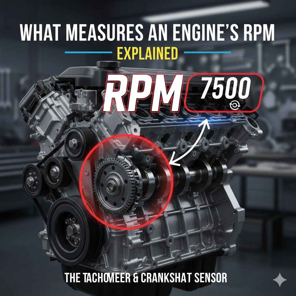
The Crankshaft Position Sensor
The main component that measures an engine’s RPM is the crankshaft position sensor. This small but vital sensor is mounted near the crankshaft, which is the rotating shaft that connects to the pistons. The crankshaft has a series of notches or teeth along its circumference.
As the crankshaft spins, these teeth pass by the sensor. The sensor is typically a type of magnetic pickup or Hall effect sensor.
When a tooth passes the sensor, it creates a change in the magnetic field. This change generates an electrical pulse. The frequency of these pulses is directly proportional to the speed of the crankshaft’s rotation.
The faster the crankshaft turns, the more teeth pass the sensor per second, and the more electrical pulses are generated. This is the raw data that tells us about the engine’s speed. The engine control unit (ECU) uses these pulses to calculate the RPM.
How The Crankshaft Position Sensor Works
A common type of crankshaft position sensor is the variable reluctance sensor. This sensor has a magnet and a coil of wire. As a metal tooth on the crankshaft’s reluctor wheel approaches the sensor, it concentrates the magnetic field.
When the tooth moves away, the magnetic field weakens. This fluctuating magnetic field induces a voltage in the coil. The voltage signal produced is an alternating current (AC) signal.
The amplitude and frequency of this AC signal change with the crankshaft speed.
Another type is the Hall effect sensor. This sensor uses a semiconductor material that changes its electrical resistance when exposed to a magnetic field. As the teeth on the crankshaft wheel pass by, they either strengthen or weaken the magnetic field around the Hall effect sensor.
This causes a change in the sensor’s output voltage, typically producing a square wave signal. This digital signal is easier for the ECU to process. Both types effectively translate the physical rotation of the crankshaft into an electrical signal.
The Role of the Engine Control Unit ECU
The information from the crankshaft position sensor is sent to the engine control unit, or ECU. The ECU is essentially the brain of the engine. It receives signals from many different sensors around the car, including the crankshaft position sensor.
It processes this data and makes decisions to control various engine functions. For RPM measurement, the ECU counts the number of pulses it receives from the crankshaft position sensor over a specific period of time.
By knowing how many teeth passed by in, say, one second, the ECU can calculate the rotational speed. For example, if the crankshaft has 60 teeth and the sensor detects 600 pulses per second, it means the crankshaft completed 10 full rotations in that second (600 pulses / 60 teeth per rotation = 10 rotations). If each rotation takes one second, then the speed is 10 revolutions per minute (RPM).
The ECU then multiplies this by 60 to get the standard RPM reading. This calculation is done thousands of times per minute to provide a continuous and accurate display.
Processing The Sensor Data
The ECU’s processing of sensor data is incredibly fast. It uses sophisticated algorithms to ensure the RPM reading is precise. Even slight variations in engine speed are detected and reflected on the tachometer.
The ECU also uses the crankshaft position information for other critical engine operations, such as determining ignition timing and fuel injection timing. This ensures that the engine runs efficiently and smoothly. The ECU constantly monitors the engine’s performance and adjusts parameters as needed, making the RPM reading a dynamic piece of information.
The ECU often compensates for variations in the number of teeth on the crankshaft wheel. Some engines might have a missing tooth or a gap in the reluctor wheel, which helps the ECU determine the exact position of the crankshaft within its rotation cycle. This adds another layer of precision to the RPM calculation.
The ECU’s ability to interpret these signals and provide accurate feedback is a testament to modern automotive technology.
Components Involved In Measuring RPM
Beyond the primary sensor, several other components play a role in the overall RPM measurement system. Understanding these interconnected parts helps paint a fuller picture of how your engine’s speed is displayed. We will look at the wiring, the dashboard display, and even the software that translates raw data into a readable format.
Each piece is essential for the system to function correctly, from the moment the crankshaft turns to when you see the needle move.
Wiring Harnesses And Connectors
The electrical signals generated by the crankshaft position sensor need to travel to the ECU. This is accomplished through the vehicle’s wiring harness. The harness is a bundle of wires that connect various sensors, actuators, and electronic modules.
The wires connecting the crankshaft position sensor to the ECU are specifically designed to transmit these electrical pulses reliably. They are usually shielded to prevent interference from other electrical components in the car, which could corrupt the signal.
Connectors are used to link the sensor to the harness and the harness to the ECU. These connectors must be clean and secure to ensure good electrical contact. Corrosion or loose connections can lead to intermittent signals or a complete loss of signal, which would prevent the RPM from being displayed or cause engine performance issues.
The integrity of the wiring system is therefore crucial for accurate RPM measurement and overall engine management. Proper maintenance of these connections can prevent many electrical gremlins.
The Tachometer Display
The information processed by the ECU is then sent to the tachometer, which is the instrument on the dashboard that displays the engine’s RPM. Older vehicles might have an analog tachometer with a needle that sweeps across a dial marked with numbers representing thousands of RPM. Modern vehicles often feature digital tachometers, which display the RPM as a numerical readout.
Regardless of the display type, they are all receiving the same processed signal from the ECU.
The tachometer needs to be calibrated correctly to accurately reflect the ECU’s output. The ECU provides a specific voltage or data stream that the tachometer interprets. The design of the tachometer itself, whether analog or digital, determines how this information is visually presented to the driver.
The goal is to give the driver a clear and immediate understanding of the engine’s operating speed, which is important for performance driving and fuel efficiency.
Digital Vs. Analog Tachometers
Analog tachometers use a mechanism, often an electric motor controlled by the ECU, to move a needle. The ECU sends a signal that tells the motor how far to move the needle, indicating the RPM. This can provide a more intuitive visual representation of engine speed changes for some drivers.
The sweeping motion can offer a sense of the engine’s responsiveness.
Digital tachometers, on the other hand, directly display the numerical value calculated by the ECU. This offers a precise reading of the exact RPM at any given moment. While some drivers miss the aesthetic of an analog needle, the clarity and precision of a digital readout are undeniable.
Many modern cars combine both, offering a digital readout within an analog-style gauge for the best of both worlds.
Factors Affecting RPM Measurement Accuracy
While the system for What Measures an Engine’s RPM? Explained Simply is generally robust, several factors can influence the accuracy of the readings. These can range from simple wear and tear to more complex electronic issues.
Knowing these potential problems helps in diagnosing any discrepancies you might notice with your car’s tachometer. It also highlights why regular maintenance is so important for your vehicle’s systems.
Sensor Wear And Tear
Like any component in a car, the crankshaft position sensor can wear out over time. Exposure to heat, vibration, and oil can degrade its internal components. A worn-out sensor might start producing inconsistent signals or weak pulses.
This can lead to inaccurate RPM readings or the tachometer flickering erratically. In severe cases, a faulty sensor can cause the engine to stall or run very poorly because the ECU is not receiving proper timing information.
The reluctor wheel on the crankshaft can also be damaged. If the teeth become worn down, chipped, or bent, they might not trigger the sensor correctly. This can lead to incorrect pulse counts and thus inaccurate RPM measurements.
Regular inspections of these components during scheduled maintenance can catch potential problems before they become serious.
Electrical Interference And Faulty Wiring
The electrical pulses from the crankshaft position sensor are quite small. They can be susceptible to interference from other electrical systems in the vehicle, such as the ignition system or the alternator. If the wiring is not properly shielded or if there is a short circuit, external electromagnetic fields can distort the sensor’s signal.
This interference can cause the ECU to misinterpret the pulses, leading to incorrect RPM readings.
Faulty wiring can also be a source of error. Damaged insulation, corroded connectors, or loose connections can impede the signal or introduce noise. If the wires are frayed or broken, the signal might be intermittent, causing the tachometer to jump around or drop to zero.
Ensuring that all wiring is in good condition and connections are clean and tight is vital for accurate readings.
ECU Malfunctions
While less common, the ECU itself can sometimes malfunction. If the ECU’s internal processing unit or its software has an error, it might not correctly calculate the RPM from the sensor data. This could lead to consistently incorrect readings or a complete failure of the tachometer to display any RPM.
Diagnosing an ECU malfunction usually requires specialized diagnostic equipment and expertise.
Sometimes, a software glitch within the ECU can cause temporary issues. A reboot of the ECU, often done by disconnecting the battery for a period, can sometimes resolve minor software-related problems. However, persistent issues typically point to a hardware problem within the ECU that requires professional attention.
The ECU is a complex computer, and like any computer, it can experience problems.
Real-World Examples And Scenarios
To better illustrate how RPM measurement works, let’s look at some practical examples. These scenarios show how the system functions in everyday driving and what might happen when things don’t go as planned. Understanding these situations can help you recognize potential issues with your own vehicle.
It also provides context for why accurate RPM readings are important for the driver.
Scenario 1 Driving Uphill
Imagine you are driving your car up a steep hill. As you ascend, the engine has to work harder to maintain speed. The crankshaft begins to spin faster to generate more power.
The crankshaft position sensor detects this increased speed and sends more frequent electrical pulses to the ECU. The ECU processes these pulses and displays a higher RPM reading on the tachometer. This higher RPM indicates that the engine is operating at a faster rotational speed, providing the necessary power to overcome the incline.
You might see the needle climb from 2,000 RPM to 3,500 RPM, for instance.
Scenario 2 Idling In Traffic
When your car is stopped in traffic, the engine is running, but the wheels are not turning. In this idle state, the engine is spinning at its lowest operational speed. The crankshaft position sensor will detect relatively few pulses per second, indicating a low rotational speed.
The ECU interprets this as the idle RPM, which for most cars is around 600 to 900 RPM. This low reading on the tachometer tells you the engine is idling and not actively propelling the vehicle.
Scenario 3 A Faltering Tachometer
Let’s say your car’s tachometer suddenly starts jumping erratically between 1,000 RPM and 3,000 RPM while you are driving at a steady speed. This could indicate a problem with the crankshaft position sensor or its wiring. The sensor might be sending inconsistent pulses due to wear or electrical interference.
The ECU is receiving faulty data and is unable to provide a stable RPM reading. You might also notice the engine running rough or hesitating during acceleration.
Case Study A Classic Car Restoration
A mechanic is restoring a classic muscle car. The original tachometer was damaged beyond repair. To
Case Study B Modern Vehicle Diagnostics
A driver notices their car’s engine light has come on, and the engine is running poorly. A mechanic connects a diagnostic scanner to the car’s OBD-II port. The scanner reads error codes related to the crankshaft position sensor circuit.
By examining the live data feed from the scanner, the mechanic can see the RPM readings fluctuate wildly. This confirms the diagnosis: the crankshaft position sensor is failing, affecting the ECU’s ability to accurately manage engine timing and fuel delivery. Replacing the sensor resolves the issue.
Troubleshooting Common RPM Issues
When your tachometer isn’t behaving as expected, there are a few common areas to investigate. Understanding these troubleshooting steps can save you time and money. It’s about systematically checking the most likely culprits first before moving on to more complex possibilities.
This approach is key to solving many car problems efficiently.
Checking The Crankshaft Position Sensor
The first step is often to inspect the crankshaft position sensor itself. This involves visually checking it for any obvious damage, cracks, or signs of oil contamination. The electrical connector should be unplugged, and the pins should be checked for corrosion or bent terminals.
A multimeter can be used to test the sensor’s resistance and its output signal when the engine is cranked. This helps determine if the sensor is functioning within its specifications.
A common test involves using an oscilloscope to view the waveform produced by the sensor as the engine is turned over manually or by the starter. A clean, consistent waveform indicates a healthy sensor. Any dropouts, erratic signals, or weak pulses suggest a problem with the sensor or its connection to the crankshaft.
Inspecting Wiring And Connectors
Damage to the wiring harness is another frequent cause of RPM issues. You should inspect the entire length of the wire connecting the crankshaft position sensor to the ECU. Look for any signs of abrasion, cuts, or melted insulation.
Pay close attention to areas where the harness might rub against engine components. All connectors along the path should be checked for secure fit and cleanliness.
Testing continuity of the wires using a multimeter is essential. This ensures that there are no breaks in the wires. Resistance checks can also identify poor connections or high resistance points that could impede the signal.
A poor connection at a connector can be as detrimental as a broken wire.
Understanding Dashboard Warning Lights
If the RPM issue is accompanied by a check engine light, it’s a strong indicator that the ECU has detected a problem. Reading the error codes stored in the ECU is crucial. These codes often directly point to the component or system that is malfunctioning.
For example, a P0335 code typically relates to a crankshaft position sensor “A” circuit malfunction. This code provides a starting point for further investigation.
Don’t ignore dashboard warning lights. They are there to alert you to potential issues that could affect your car’s performance, safety, or longevity. Even if the car seems to be running okay, a stored code indicates a problem that might worsen over time or lead to more significant issues.
Frequently Asked Questions
Question: What is the main component that measures engine RPM
Answer: The crankshaft position sensor is the primary component that measures an engine’s RPM by detecting the rotation of the crankshaft.
Question: How does the ECU use the sensor data
Answer: The ECU counts the electrical pulses from the sensor over time to calculate the engine’s rotational speed in revolutions per minute.
Question: Can a dirty sensor affect RPM readings
Answer: Yes, dirt or debris on the sensor or its target wheel can interfere with its ability to generate accurate signals, leading to incorrect RPM readings.
Question: What happens if the crankshaft position sensor fails
Answer: A failed sensor can cause the engine to not start, stall, run poorly, and the tachometer will likely stop working or display inaccurate readings.
Question: Are all RPM measurement systems the same
Answer: While the core principle is the same, the specific types of sensors, number of teeth on the reluctor wheel, and ECU programming can vary between different vehicle makes and models.
Summary
The engine’s RPM is measured by a crankshaft position sensor. This sensor detects the spinning crankshaft and sends electrical pulses to the ECU. The ECU counts these pulses to calculate the engine’s speed.
This information is then displayed on the tachometer on your dashboard, showing you how fast your engine is running.