Ford 302 Engine Diagram: A Field Manual for DIY Repairs
You pop the hood on your classic Mustang or F-150, and you’re staring at a mess of hoses, brackets, and pulleys. You know it’s a 302, but you can’t tell if that leak is from the water pump or the intake manifold gasket. You need a map.
A Ford 302 engine diagram is that map. It shows you where every major component lives, how the belts route, and which vacuum line goes where. More importantly, it tells you what to check when something goes wrong. This guide walks you through the diagram, the firing order, the torque specs that matter, and the spots where these engines commonly fail.
I have spent years wrenching on these small blocks. I have seen the same mistakes repeated by new owners who skipped the diagram and just started pulling parts. This is the guide I wish I had on my first 302 build. You will walk away knowing exactly how to read the diagram and use it for real repairs.
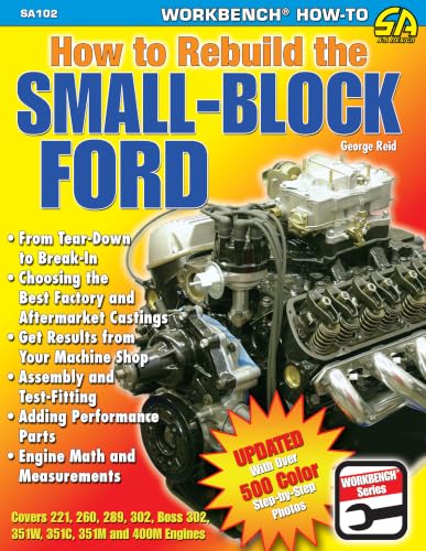
If you are planning a full teardown, a book like How to Rebuild the Small-Block Ford from S-A Design is worth having on the bench. It covers the disassembly, machining, and reassembly steps in detail, which pairs well with the visual reference we cover here.
Why You Need a Ford 302 Engine Diagram
You can’t fix what you can’t identify. A diagram turns a confusing tangle of components into a clear layout. It helps you name the part before you order it.
Consider the alternator bracket. On a 302, there are at least three different bracket styles depending on the year and whether the car had air conditioning. Without a diagram, you might buy the wrong bracket and waste a weekend.
The diagram also helps you trace systems. If you have an overheating issue, you can visually follow the coolant path from the water pump through the block and into the radiator. You can spot a pinched hose or a leaking thermostat housing quickly.
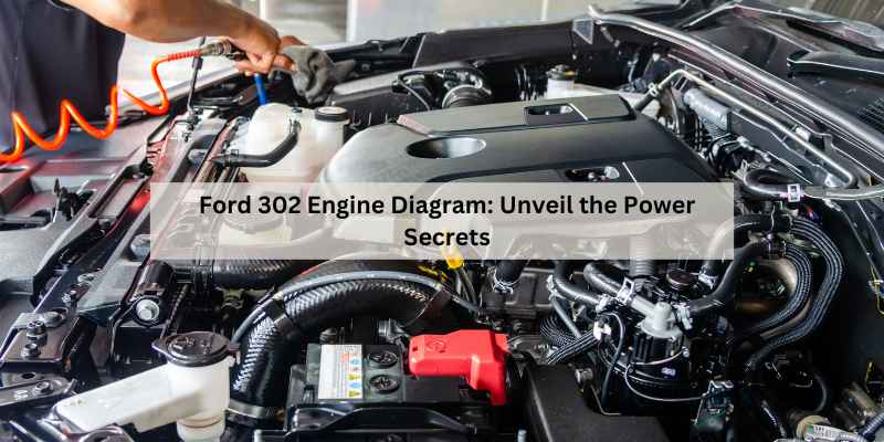
Complete Ford 302 Engine Diagram (Labeled)
Think of the 302 as a collection of systems bolted to a cast-iron block. The front of the engine holds the accessory drive, the top holds the intake and valve covers, and the bottom holds the oil pan. Here is the breakdown of each major area.
Front Accessory Drive and Belt Routing
The front of the engine is the busiest area. You have the crankshaft harmonic balancer at the bottom center. That balancer is critical—it dampens vibration and also serves as the main pulley for the serpentine belt or V-belts.
On serpentine belt setups (common from the mid-1980s onward), the belt routes around the crankshaft pulley, water pump pulley, alternator, and sometimes a power steering pump. The belt tensioner keeps everything tight. On older V-belt setups, you have multiple belts, each driving one or two accessories.
The water pump sits directly above the balancer. It has a small weep hole on the bottom. If you see coolant dripping from that hole, the pump’s internal seal is failing. That is a common failure point you can spot right on the diagram.
The alternator mounts on the passenger side (right side when facing the engine) on most models. The power steering pump, if equipped, sits on the driver’s side. The smog pump, found on many 1970s and 1980s models, bolts to the front of the passenger side head.
Intake and Exhaust Systems
The intake manifold sits in the center of the engine, between the two cylinder heads. On a stock 302, it is usually a two-piece design with a lower manifold and an upper manifold or a single-plane unit on older models. The carburetor or throttle body mounts on top.
The exhaust manifolds bolt to the outside of each cylinder head. They route hot gases into the exhaust pipes. Cast-iron manifolds are prone to cracking, especially around the bolt holes. A diagram helps you identify the manifold and its gasket surface.
Look for the EGR valve on later models. It mounts on the intake manifold and has a metal tube running to the exhaust. Carbon buildup often clogs the EGR passage, causing a rough idle. The diagram shows you exactly where to look.
Cooling and Lubrication Systems
The cooling system starts at the water pump, which pushes coolant into the block. It flows around the cylinders, up through the intake manifold, and out to the thermostat housing at the front. The thermostat opens at 180 or 195 degrees to let coolant flow to the radiator.
The oil system is simpler. The oil pump sits in the oil pan, driven by a shaft from the distributor. It pushes oil through a filter and into the main oil galleries. The oil pressure sender, usually located near the distributor, sends a signal to the gauge. Low oil pressure often points to a worn pump or a clogged pickup screen.
The oil pan is a stamped steel pan that holds about 5 quarts. The drain plug is at the bottom rear on most models. If you see leaks, check the pan gasket and the rear main seal first.
Ford 302 Firing Order and Cylinder Numbering
This is the part that confuses everyone. The firing order for a 302 is 1-5-4-2-6-3-7-8. That is the order in which the spark plugs fire.
Cylinder numbering is not sequential down one side. The cylinders on the driver’s side are 1, 2, 3, and 4, starting from the front. The passenger side cylinders are 5, 6, 7, and 8, also starting from the front.
So cylinder 1 is the front driver’s side, and cylinder 5 is the front passenger side. The distributor rotor spins counterclockwise. When you set the timing, you point the rotor at the number 1 spark plug wire terminal on the distributor cap.
Get this wrong, and the engine will backfire or run rough. Double-check the firing order against the diagram before you connect the plug wires. A simple mistake here costs you an afternoon of chasing a misfire.
Year-Specific Variations (Pre-1981 vs. Post-1981)
The 302 changed over the years, and the diagram changes with it. The most important split is 1981.
Pre-1981 models used a carburetor and a traditional distributor with a vacuum advance. The vacuum routing is complex. You have a vacuum line from the intake manifold to the distributor, another to the transmission modulator, and several to the emissions equipment. A single cracked or disconnected line can cause a rough idle or a hard shift.
Post-1981 models, especially from 1985 onward, used electronic fuel injection (EFI) and a computer-controlled distributor. The vacuum lines are fewer, but you have more electrical connectors. The firing order remained the same, but the distributor setup changed. The EEC-IV system controls timing electronically, so there is no vacuum advance canister.
If you have a 1979 model, you need the pre-1981 diagram. If you have a 1986 model, you need the EFI diagram. Using the wrong one leads to misdiagnosis.
How to Use the Diagram for Common Repairs
A diagram is not just a picture. It is a diagnostic tool. Here is how to use it for two common jobs.
Tracing Vacuum Lines
Vacuum leaks are the most common cause of a rough idle on carbureted 302s. Start at the intake manifold vacuum port. Follow each line from the diagram to its destination.
Check the line to the brake booster first. It is the largest line, and it cracks at the connection. Then check the line to the PCV valve on the valve cover. A torn PCV grommet causes a massive leak.
Use a can of carb cleaner and spray it around suspected areas while the engine idles. If the idle smooths out, you found the leak. The diagram tells you where to spray.
Replacing the Water Pump or Alternator
For a water pump replacement, drain the coolant first. Remove the fan shroud and the fan. Then loosen the belt tensioner to remove the serpentine belt. Unbolt the pump from the timing cover. There are about six bolts. Clean the gasket surface thoroughly before installing the new pump.
For the alternator, disconnect the battery first. Remove the belt from the alternator pulley. Unbolt the pivot bolt and the adjusting arm bolt. Slide the alternator out. The diagram shows the bracket layout, which helps you avoid removing the wrong bolt and dropping the bracket.
Torque the water pump bolts to 12-18 ft-lbs. The alternator bracket bolts are usually 30-40 ft-lbs. Check the diagram for the specific bolt locations.
Critical Torque Specifications Table
Torque specs are not suggestions. Over-tightening a head bolt can strip the threads in the block. Under-tightening an intake manifold bolt causes a vacuum leak. Here are the numbers you need.
| Component | Torque Spec (ft-lbs) | Notes |
|---|---|---|
| Cylinder head bolts | 65-72 | Use a two-step tightening sequence; follow the factory order |
| Intake manifold bolts | 23-25 | Tighten from the center outward in three steps |
| Main bearing cap bolts | 60-70 | Apply light oil to threads before torquing |
| Connecting rod bolts | 19-24 | Use a torque wrench; do not guess |
| Water pump bolts | 12-18 | Small bolts, easy to strip |
| Harmonic balancer bolt | 70-90 | This bolt holds the balancer on the crank snout |
| Rocker arm studs | 17-23 | Check for stripped threads on these |
These specs apply to stock fasteners. If you use aftermarket studs or bolts, check the manufacturer’s instructions. They often require different torque values.
Common Failure Points to Inspect
You can spot most 302 problems just by looking at the diagram and then checking the part.
The timing chain is a known weak point. It stretches over time, causing the camshaft timing to retard. You can check for slack by removing the distributor cap and turning the crankshaft back and forth. If the rotor moves more than a few degrees before the camshaft moves, the chain is worn. A worn chain causes poor performance and backfiring.
The water pump weep hole is another easy check. Look for dried coolant residue around the hole at the bottom of the pump. If you see it, the pump is on its way out.
The intake manifold gaskets leak coolant externally. You will see a green or orange stain on the side of the block below the manifold. The leak often appears at the front or rear corners of the manifold.
The harmonic balancer can separate. The outer ring slips on the rubber inner layer. You will see a wobble at idle or a distinct squeal. Check the alignment marks on the balancer. If they are off, replace it.
Oil leaks are common at the rear main seal and the valve cover gaskets. The rear main seal requires dropping the oil pan and transmission to replace. Valve cover gaskets are a simple swap, but you must clean the surfaces well to prevent future leaks.
Ford 302 Engine Reliability and Maintenance Tips
The 302 is a reliable engine, but it rewards regular maintenance. Oil changes every 3,000 miles with a quality filter keep the hydraulic lifters quiet. Ignore this, and the lifters will start ticking.
Coolant needs replacement every two years. Old coolant becomes acidic and eats the gaskets. Flush the system and use a 50/50 mix of antifreeze and distilled water.
Check the belt tension regularly. A loose serpentine belt squeals and under-drives the alternator and water pump. Replace the belt every 50,000 miles or sooner if you see cracks.
These engines are not perfect. The factory camshaft is mild, and the heads do not flow great. But they run forever with basic care. Many of these engines have gone 200,000 miles without a rebuild.
If you own a truck with a 302, you might also want to check the undercarriage diagram for your F-150 to see the full drivetrain layout. And if you are dealing with a specific issue like a failsafe mode, this failsafe reset guide covers the steps. For the later 4.6-liter modular engine, which is a different animal entirely, see this 4.6 engine overview.
Final Thoughts on Using the Diagram
- Always verify the year of your engine. Pre-1981 and post-1981 diagrams differ in vacuum routing and ignition.
- Memorize the firing order: 1-5-4-2-6-3-7-8. The distributor rotates counterclockwise.
- Keep the torque spec table handy. Over-tightening is worse than under-tightening.
- Check the water pump weep hole and the harmonic balancer for wear at every oil change.
- Use the diagram to trace vacuum lines before you start pulling parts. It saves hours.
- Replace the timing chain if you see more than 5 degrees of slack at the distributor rotor.
- Stick to a 3,000-mile oil change interval. It is cheap insurance for a long-lived engine.
Products related to this article
Sponsored / affiliate links. As an Amazon Associate I earn from qualifying purchases. I may earn additional commission from eligible campaigns.