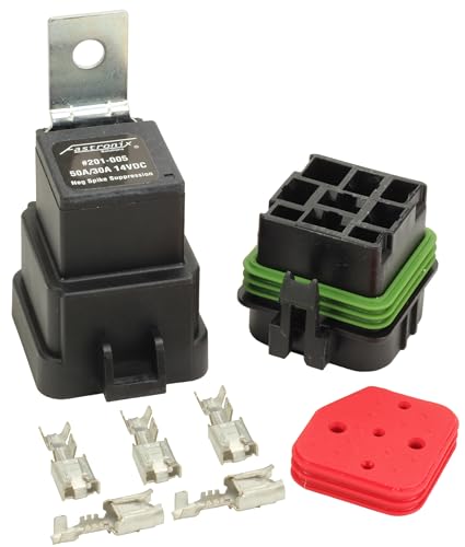

Relays for Cars: Tested & Reviewed (2 Picks)
For car and truck diagnostics, pick a relay tester with two functions: one that checks coil strength for weak relays, and one that lets you wiggle, heat, or tap for intermittent faults. Miss the right test, and you can replace a good relay, chase the wrong circuit, or leave a failure that comes back. This guide compares two relay testers by the exact fault they diagnose best, including awkward relay shapes and relay-versus-circuit confusion.
What relay testers catch and what they miss?


An automotive relay tester can do two different jobs. A continuity-style check tells you whether the coil and switch path are present, while a load test stresses the relay so weak contacts show up under use. That difference matters because a relay can pass a simple check and still fail when current flows.
Relay pin layout matters too. Most common automotive relays use 85 and 86 for the coil, 30 as common, 87 as normally open, and 87a as normally closed. If you do not match the pin layout in the service information, the wrong test can make a good relay look bad.
Open coil versus burned contacts
An open coil usually shows up as no magnetic pull at all. A burned contact can still click and still fail under load. The second failure is harder to catch because the relay appears alive until current demand exposes high resistance, heat, or voltage drop.
Intermittent drop-out versus socket wiring fault
Intermittent drop-out points to a relay that works, then quits when vibration, heat, or movement changes the connection. Socket wiring faults create a similar symptom, but the relay itself may be fine. That is why a tester that can separate relay behavior from the vehicle circuit is more useful than a yes-or-no continuity check.
Why continuity checks can miss a weak relay
Continuity only proves a path exists. It does not prove the contacts can carry current without collapsing. A weak relay with pitted contacts can still show continuity on a meter, then fail as soon as a fan motor, fuel pump, or other load pulls current through it.
Low system voltage skews the result here. One competitor lists an operating window of 11V to 15V, and that limit shows why you should verify battery and charging voltage before blaming the relay. If supply is weak, the tester may point at the relay when the fault starts with the vehicle battery or charging state.
Relay tester comparison table
| Model | Best at | Voltage support | Relay fit | Test style | Result feedback |
|---|---|---|---|---|---|
| Electronic Specialties 194 Super Relay Buddy | Weak contacts and repeatability | 12V | Seven 12V relay types; 4-pin and 5-pin support | Automated load test, 10-cycle sequence | Green, red, or yellow lights |
| Lisle 60150 Relay Pro | Mixed-fleet work and awkward access | 12V and 24V DC | Most 4-pin and 5-pin spade relays | Manual push-button operation | Operator interprets the result |
| Electronic Specialties 195 Super Relay Buddy Pro Kit | Odd relay footprints | 12V-only | Specialty relay adapters | Load test with adapters | Pass/fail style with kit-based setup |
| Autel PowerScan PS100 | Circuit-versus-relay confusion | 12V and 24V | Not relay-specific | Instant power and ground apply | Probe-style diagnostics |
Relay tester decision table
| Symptom | Likely failure mode | Best test method | Recommended tester type |
|---|---|---|---|
| No-start | Open coil, bad feed, or socket wiring fault | Verify coil pins 85 and 86, then check load side at 30 and 87 | Load tester first, then power probe if circuit fault is suspected |
| Intermittent fuel pump | Weak relay contacts or drop-out under vibration | Repeated cycle testing under load | Automated relay tester with repeat cycles |
| Fan inoperative | Burned contacts, blown feed, or control fault | Load test the relay, then confirm power and ground at the socket | Load tester plus power probe |
| Relay clicks but load drops out | High-resistance contacts | Apply current, not just continuity | 7+ amp load tester |
| Odd relay footprint | Specialty relay shape, adapter mismatch | Use the proper adapter or clipped leads | Kit with specialty adapters |
| 24V truck application | Voltage mismatch if a 12V-only tool is used | Match the tester to system voltage before any relay check | 12V/24V relay tester or probe |
Electronic Specialties 194 super Relay Buddy vs Lisle 60150 Relay Pro
The choice comes down to test style and vehicle mix. The Electronic Specialties 194 Super Relay Buddy is the stronger choice for repeatable diagnosis of weak or intermittent 12V relays, while the Lisle 60150 Relay Pro is better when the vehicle mix includes 24V trucks or when clipped-in access matters more than automation.
Load strength and test method
The 194 applies a full 7+ amp load, then runs an automated 10-cycle test sequence. That combination is useful when the relay problem is repeatable only under stress. It also gives green, red, or yellow results, which makes pass/fail screening faster than interpreting a single meter reading.
The Lisle appears to use manual push-button operation. That gives the operator more control over when to apply power and how long to hold the test, which helps when you want to duplicate a symptom in a truck bay or under awkward packaging.
Voltage support and vehicle type
The 194 is aimed at 12V relay work. The Lisle supports both 12V and 24V DC relays, so it fits mixed-fleet service better. For diesel trucks, municipal equipment, and other 24V systems, that extra voltage range can keep you from reaching for the wrong tool.
That matters because a 12V-only tester can mislead you in truck work even if the relay itself is good. Matching the tool to the system is part of the diagnosis, not a convenience detail.
Relay fit and pin-layout coverage
The 194 tests seven 12V relay types out of the box and supports 4-pin and 5-pin relays. The Lisle uses universal alligator clips for most 4-pin and 5-pin spade relays. In practice, that makes the Lisle the more flexible choice when the relay is not a neat plug-in shape.
For specialty shapes, the Electronic Specialties 195 Super Relay Buddy Pro Kit goes further with shielded adapters for unusual relay footprints. That makes it a better fit when the relay is a BMW or Mini style oddball and the standard sockets do not line up cleanly.
Result indicators and operator feedback
The 194 gives the clearest quick read because the result lights are built into the test process. Green, red, or yellow is easier to act on when you are screening multiple relays on the same job. The Lisle is still useful, but it relies more on the operator watching the effect of the manual test.
Picture a fuel pump relay that clicks on the bench but fails once warmed up in the car. A continuity check may still look fine. A load test with repeated cycles is the better way to catch that kind of weak-contact failure.
Which tester fits your relay problem?
Pick the tester around the symptom, not the label on the box. Weak contacts, intermittent dropout, socket confusion, awkward relay shapes, and 24V use each point to a different tool. The wrong choice can turn a five-minute check into a parts cannon session.
Weak relay contacts and repeatability
If the relay clicks but the load still falls off, start with a tester that applies current. The 194 is stronger here because it loads the relay with 7+ amp pressure and repeats the cycle automatically. That makes it better for weak-contact diagnosis than a continuity-only approach.
Intermittent faults that need an automatic cycle test
If the symptom comes and goes, repeated cycling matters. An automatic 10-cycle test can expose a relay that fails after heating up, sticking, or bouncing under vibration. That is where the 194 saves time because it keeps the sequence consistent.
Mixed-fleet work with 12V and 24V vehicles
If your bay sees both passenger cars and 24V trucks, the Lisle 60150 Relay Pro is the more practical tool. Its 12V and 24V DC support removes a common mismatch problem and makes it a better fit for mixed fleets.
Awkward relay shapes and clipped-in access
If the relay footprint is unusual, the Pro Kit or the Lisle style clip setup is often the safer route. Specialty adapters solve shape problems that a standard socket tester cannot. A common first-timer mistake is forcing a relay into the wrong interface and then blaming the relay for the poor fit.
- Confirm the battery is within the test window the tool requires.
- Identify the relay pins in the service manual: 85, 86, 30, 87, and 87a.
- Decide whether the symptom suggests coil failure, contact wear, or a circuit fault.
- Use a load test for weak contacts and an automatic cycle test for intermittent faults.
- Use a power probe or jumper kit when the socket or circuit itself needs diagnosis.
Choose Electronic Specialties 194 Super Relay Buddy if… / Choose Lisle 60150 Relay Pro if…
Choose Electronic Specialties 194 Super Relay Buddy if you want faster pass/fail screening on 12V relays, especially when the concern is weak contacts. It is the better choice if you need an automated 10-cycle test, built-in green/red/yellow results, or repeat checks on seven 12V relay types.
Choose Lisle 60150 Relay Pro if you work on both 12V and 24V vehicles, need universal alligator clips for most 4-pin and 5-pin spade relays, or prefer manual push-button control. It suits truck work and mixed access better, even if it asks more from the operator.
What about 24V and specialty relays?
24V and specialty relays are where many comparison pages go thin. The issue is not only voltage. It is also shape, access, and whether the tester can actually connect without forcing the pins. BMW and Mini style quirks often matter here because the relay package may not behave like a plain 4-pin cube.
Why pin layout still matters
Even on specialty work, the pin map still decides the test. Coil pins 85 and 86 must be identified correctly, and the load path through 30 and 87 or 87a must match the circuit design. If the relay is a normally closed type, using the wrong contact path can create a false failure.
When a power probe or jumper kit beats a relay-only tester
Use a power probe or jumper kit when the relay may be innocent and the circuit is the real issue. If power is missing at the socket, the relay tester alone will not show the broken feed, blown fuse, or ground fault upstream. That is where circuit diagnosis beats relay replacement.
Frequently asked questions
How to test vehicle relays
Start by confirming the relay pin layout and system voltage. Then check the coil at 85 and 86, and test the switched path at 30 and 87 or 87a under load, not just with continuity. If the relay passes on the bench but fails in the vehicle, inspect the socket and circuit next.
Which relay tester works best for 4 and 5 pin relays?
For standard 4-pin and 5-pin relays, the best choice depends on the fault. Use the one that matches the symptom and vehicle type.
What is a relay on a vehicle?
A vehicle relay is a switch that lets a small control signal operate a higher-current circuit such as a pump, fan, starter, or lights. The useful part for diagnosis is not the definition itself, but the pin map and load behavior. That is what tells you whether the relay or the circuit is at fault.
How to test auto relays
Auto relays should be tested with the system voltage they were designed for and with enough load to expose weak contacts. A continuity-only meter check can miss a relay that fails under current. If the relay is unusual or the vehicle is 24V, use a tester or probe that matches the application.
Products related to this article
Sponsored / affiliate links. As an Amazon Associate I earn from qualifying purchases. I may earn additional commission from eligible campaigns.