Car Sensors and Parts Guide: Roles, Symptoms, Fixes
A car sensors and parts guide starts with four checks: what it reads, where it sits, what symptoms or codes it causes, and whether the fault is sensor, wiring, or assembly. I have seen that call go wrong many times, and it leads people to buy the wrong part, miss a bad wheel hub, or chase a no-start that is only a broken wire. This guide links common sensors to their job, location, symptoms, fitment differences, and the right fix path. If you want the short answer first, most sensor problems are solved faster when you confirm the signal on a scan tool, verify power and ground, inspect the connector and nearby mechanical parts, and only then order the exact fitment.
How car sensors, parts, and the ECU work together
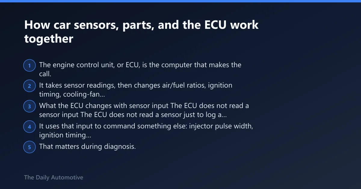


The engine control unit, or ECU, is the computer that makes the call. It takes sensor readings, then changes air/fuel ratios, ignition timing, cooling-fan operation, idle control, throttle response, shift strategy on many vehicles, and emissions functions so combustion and drivability stay within target.
What the ECU changes with sensor input
The ECU does not read a sensor just to log a number. It uses that input to command something else: injector pulse width, ignition timing advance, electronic throttle angle, radiator fan operation, purge flow, torque management, or transmission behavior.
That matters during diagnosis. I have chased rough idle complaints with a throttle position code that turned out to be a vacuum leak, a carbon-packed throttle plate, low battery voltage, or damaged wiring. The code points to a circuit or behavior. It does not prove the sensor itself failed.
Sensor, circuit, actuator, and assembly: the parts terms that matter when buying
Buying the right part starts with the right noun. A sensor reads a condition. A circuit includes the sensor, wiring, connector, grounds, and ECU input. An actuator does work, such as a throttle motor. An assembly may bundle several pieces into one service part.
That is where many ordering mistakes happen. A throttle position sensor may be sold on some engines as a separate bolt-on unit, but on many electronic throttle systems it comes only with the full throttle body. An ABS sensor may be separate on one trim and built into the wheel hub on another.
Why a sensor code does not always mean the sensor is bad
Common lookalikes include exhaust leaks ahead of an oxygen sensor, oil-soaked connectors at pressure senders, split intake boots near a MAF sensor, coolant loss causing false temperature complaints, and rusty tone rings upsetting wheel-speed readings.
Stop replacing parts and test the circuit when the new sensor gives the same code, live data is implausible across more than one related sensor, reference voltage is missing, or the fault appears only during wiring movement, rain, heat soak, or engine torque movement. That is the point for circuit tracing and ECU input testing.
For a basic consumer overview of common sensor types, see Types Of Car Sensors And What They Do [Guide] – Auto Chimps.
What sensors are in a car and what do they do?
Cars group sensors by system. In the shop, I think of them as engine management sensors for air, throttle, crank, cam, load, knock, and temperature, exhaust sensors for emissions feedback, fluid and pressure sensors for oil and coolant, and wheel-speed and transmission sensors for braking and shifting. The ECU uses those signals to control fuel, timing, cooling, and warnings.
Engine management sensors
The core set usually includes the mass airflow sensor, manifold absolute pressure sensor, throttle position sensor, crankshaft position sensor, camshaft position sensor, intake air temperature sensor, coolant temperature sensor, and knock sensor.
The MAF sensor measures the volume of air entering the intake tube, usually after the air filter, so the ECU can meter fuel from actual airflow. The MAP sensor reads intake manifold pressure, or boost pressure on some setups, which tells the ECU how hard the engine is working. The throttle position sensor reports throttle blade angle, crank and cam sensors show exactly where the engine is in its cycle, and IAT plus coolant temperature help the ECU judge air density, warm-up fueling, and timing.
Emissions and exhaust sensors
Oxygen sensors are the main players here. Oxygen sensors monitor oxygen in exhaust gas before and after the catalytic converter. Upstream sensors shape fuel control. Downstream sensors help the ECU watch catalytic converter performance.
On newer applications, exhaust gas temperature sensors and NOx-related sensors may also be present. These are more common on diesel and late-model emissions-heavy setups, and they are often less forgiving of wiring damage and heat-soak connector failures.
Chassis, braking, and wheel-speed sensors
Wheel-speed sensors feed the ABS and stability systems. Some are separate sensors aimed at a tone ring. Others are built into the wheel bearing or hub assembly. Transmission speed sensors do similar work for shift timing and ratio checks.
These faults often feel mechanical before they look electrical: intermittent ABS lights over bumps, sudden traction-control cuts, strange speedometer behavior, or harsh shifting with no engine complaint.
Fluid level, pressure, and temperature sensors
The engine oil level sensor is usually attached to the side of the oil pan and reports low-oil status to the dash. The oil pressure sensor tells the ECU or instrument cluster when pressure is outside the expected range. Coolant temperature sensors track antifreeze temperature and affect fan control, fuel delivery, and warm-up behavior.
How many sensors are in a modern car?
There is no single exact count for every vehicle, but a typical late-model passenger vehicle usually carries about 60 to 100 sensors. Many luxury, EV, hybrid, and ADAS-heavy vehicles go well past 100, and some exceed 200 once body, safety, battery, ride, and climate systems are counted alongside the powertrain.
Typical sensor counts by vehicle class
Basic compact cars are usually near the lower end, often around the 60-sensor range. Mid-size sedans and crossovers commonly land higher because they add more wheel, body, HVAC, and transmission inputs. Luxury vehicles, large SUVs, hybrids, EVs, and advanced driver-assist platforms can move into the 100-plus range quickly.
The guide lists 15 common sensor types in vehicles, but that is a repair map, not a full vehicle inventory. The point is to focus on the families most likely to create drivability, warning-light, fuel-economy, and buying-decision questions.
How many are tied to engine management
On many gasoline vehicles, roughly 15 to 30 sensors are tied mainly to engine and emissions control. That group commonly includes MAF, MAP, TPS, IAT, coolant temperature, crank, cam, knock, upstream and downstream oxygen sensors, oil pressure, oil level, EVAP-related sensors, and in some cases boost, exhaust temperature, and fuel-pressure sensors.
Why luxury and safety-heavy vehicles carry far more sensors
Extra wheel and yaw sensors, ride-height sensors, radar and camera support inputs, seat occupancy sensors, battery monitoring, and thermal-management hardware raise the count fast. Yet the repair path still starts the same way: identify function, location, part form, and circuit integrity before ordering.
Where are the most common car sensors located?
Most common car sensors sit in predictable zones: the intake tract holds the MAF and often the IAT, the throttle body carries or contains the TPS, the engine block and head hold crank, cam, and oil pressure units, the oil pan carries the level sensor, coolant sensors sit near the thermostat housing, and O2 sensors thread into the exhaust before and after the catalytic converter.
Air intake and throttle body area
The MAF sensor is typically between the air filter and intake manifold. On many engines it sits in the intake tube or airbox outlet. Some vehicles combine the IAT with the MAF, so a bad reading may call for one assembly rather than two separate sensors.
The throttle position sensor may bolt to the side of a cable-operated throttle body, and on drive-by-wire systems it is often integrated into the throttle body assembly.
Engine block, cylinder head, and oil pan
The oil pressure sensor is often on or in the engine block near the bottom of the cylinder head. It is commonly threaded and uses one or two external pins. Crank sensors usually read a reluctor on the crankshaft near the timing cover, bellhousing, or block. Cam sensors usually sit near the valve cover or cylinder head ends.
The engine oil level sensor is usually attached to the side of the oil pan. Some pans have a direct-mounted sensor with an O-ring seal. Others use a short sub-wire lead that can fail before the sensor does.
Cooling system and thermostat housing
Coolant temperature sensors are often near the thermostat housing. They may thread into a water outlet or clip into a plastic coolant flange with a retaining clip and seal. The fitment trap here is connector style and sensor depth, especially across engine-code splits.
Exhaust system, catalytic converter, wheels, and hubs
Most modern cars have two oxygen sensors per exhaust pipe. Typically, one oxygen sensor is placed upstream before the catalytic converter, and another is placed downstream after it. Wheel-speed sensors are usually located near each hub or knuckle area, either reading a tone ring or built into the hub assembly itself.
The sensor-to-parts decision table
Use this table to move from symptom to likely part form. It separates job, location, failure signs, service form, and a fast test cue, so a rough idle, warning light, or ABS fault can be translated into a cleaner purchase decision before parts are ordered.
Sensor-to-parts decision table
| Sensor name | Location | Common failure symptoms | Replacement form factor | Standalone or assembly? | Quick test cue |
|---|---|---|---|---|---|
| Oxygen sensor, upstream | Exhaust before catalytic converter | Black smoke, sulfur smell, hesitation, surging, poor fuel economy | Threaded heated sensor with vehicle-specific connector | Usually standalone | Check live switching and heater power; inspect for exhaust leaks ahead of sensor |
| Oxygen sensor, downstream | Exhaust after catalytic converter | Catalyst-efficiency codes, emissions-readiness issues, less often drivability complaints | Threaded heated sensor | Usually standalone | Compare upstream and downstream patterns; a lazy rear sensor can mimic catalyst faults |
| MAF sensor | Between air filter and intake manifold | Hard starting, stalling, hesitation, poor performance | Insert-style sensor or full housing with screen | Either standalone insert or housing assembly | Check live airflow at idle and snap throttle; inspect for intake leaks after the sensor |
| MAP sensor | Intake manifold or charge pipe | Poor throttle response, rich or lean running, boost/load errors | Bolt-in plastic sensor with O-ring | Usually standalone | Key-on reading should match local barometric pressure trend; check vacuum source |
| Throttle position sensor | Throttle body | Hesitation, erratic idle, limp mode, shift complaints | Separate side-mounted sensor or integrated electronic throttle body | Often assembly on newer vehicles | Watch throttle angle sweep for jumps or dead spots |
| Coolant temperature sensor | Near thermostat housing | Overheating complaints, hard starts, fan issues, poor fuel efficiency | Threaded sensor or clip-in sensor with seal | Usually standalone | Compare cold-engine reading to ambient and monitor warm-up trend |
| Engine oil level sensor | Side of oil pan | Incorrect oil level reading, continuous on-off oil warnings | Pan-mounted sensor with seal and short lead | Standalone or pan/wiring related | Confirm actual oil level first; inspect connector for oil and impact damage |
| Engine oil pressure sensor | Engine block near lower cylinder head area | Oil warning light, false pressure alarms, gauge dropouts | Threaded sender with one or two pins | Usually standalone | Verify real pressure with a mechanical gauge before condemning the sender |
| Crankshaft position sensor | Block, timing cover, or bellhousing area | No-start, stall when hot, tach dropouts | Bolt-in magnetic or Hall-effect sensor | Usually standalone | Check for RPM signal during cranking; inspect reluctor damage if accessible |
| Camshaft position sensor | Cylinder head or valve cover end | Extended crank, misfire, timing correlation faults | Bolt-in sensor with O-ring | Usually standalone | Check cam/crank sync data before replacing the part |
| Knock sensor | Engine block or valley | Retarded timing, weak power, knock-related codes | Bolt-on puck-style sensor | Standalone, but access may require intake removal | Rule out actual engine noise and poor fuel before sensor replacement |
| Wheel-speed / ABS sensor | Hub, knuckle, or integrated in bearing | ABS light, traction-control activation, speed signal faults | Clip-in sensor or sensor-in-hub | Either standalone or hub assembly | Check live wheel-speed dropouts and inspect tone ring rust or cracks |
| Transmission speed sensor | Transmission case | Harsh shifts, limp mode, gear-ratio codes | Threaded or bolt-in sensor | Usually standalone | Compare input and output speed data on a scan tool |
| Exhaust gas temperature sensor | Exhaust stream near turbo or aftertreatment | Regeneration issues, heat-related derate, emissions faults | Threaded probe sensor | Usually standalone | Check temperature plausibility from cold start forward |
Fitment checks that stop ordering mistakes
- Confirm engine code, production date, and VIN split.
- Match connector shape and pin count.
- Check whether the sensor is threaded, clip-in, or bolt-on.
- Verify if the part is sold alone, with a pigtail, or only in an assembly.
- Compare old and new sensor tip length, seal style, and mounting clocking.
If you are cross-shopping related repairs, I would also compare the part form against a dedicated fitment guide for the mass air flow sensor symptoms and replacement, a position and load guide for the throttle position sensor symptoms, testing, and fitment, and a wheel-end article on ABS wheel speed sensor vs wheel hub bearing assembly. Those are the pages I would want open before ordering a standalone sensor that might actually be sold only with an assembly.
Engine air and fuel sensors: the failures that most often affect drivability
MAF, MAP, TPS, and IAT faults are among the most common causes of hesitation, idle instability, poor starting, and false fuel-trim complaints. They also create many misdiagnoses because unmetered air leaks, dirty throttle plates, weak voltage supply, and connector damage can imitate a failed sensor.
Mass airflow sensor vs manifold absolute pressure sensor
The short answer is that the MAF measures actual incoming air, while the MAP estimates engine load from manifold pressure. Some engines use both; others rely mainly on MAP plus IAT in a speed-density strategy.
A faulty MAF sensor can cause stalling, poor starting, and hesitation. It can also skew fuel trim enough to affect catalyst health over time. Before replacement, check the air filter box seal, intake boot tears after the MAF, and contamination on the sensing element. Some MAF units are serviceable inserts. Others require the full housing because the calibrated bore is part of the part.
Broadly, parts cost tends to be modest for insert sensors and higher for housing assemblies. Labor is usually easy unless access is blocked by covers or ducting.
Throttle position sensor and throttle-body integrated units
The short answer is that the throttle position sensor tells the ECU throttle angle, but on many newer cars you do not buy it separately. It often comes with the electronic throttle body.
On older cable-throttle systems, a separate TPS may be replaceable in minutes. On electronic throttle setups, the sensor and motor are often built into the throttle body, which changes the buying decision and raises parts cost.
Testing is simple in concept: look for a smooth throttle-angle sweep on live data. Sudden jumps, dropouts, or disagreement between pedal and throttle angle point to sensor, actuator, or wiring trouble. After replacement, some vehicles need a relearn procedure.
Intake air temperature sensor and combined MAF/IAT designs
The short answer is that the IAT sensor reports incoming air temperature, and on many vehicles it is integrated into the MAF. That means one bad temperature reading can become an assembly decision, not just a two-wire sensor swap.
The IAT sensor may be a separate two-wire piece in the duct or manifold, or it may be built into the MAF. If intake temperature data is wrong, cold-start fueling and load calculation can suffer. That matters when a vehicle has both an airflow code and an intake temperature plausibility code.
Crankshaft Position Sensors for High-Mileage Engines
High-mileage engines demand crankshaft position sensors with heat-rated wiring and sealed connectors to prevent no-start conditions after heat soak or stalling in traffic. OEM-equivalent units from Denso, Bosch, ACDelco, or NTK reliably match factory specifications and address common failure patterns specific to aging powertrains.
Selecting the correct replacement involves matching the sensor to your engine’s fault signature rather than simply choosing the cheapest option. This guide to high-mileage crankshaft sensors ranks top choices by application and explains when replacing the pigtail harness is necessary to avoid repeated failures on brittle wiring.
Cost breakdowns for crankshaft position sensor repairs
Replacing a crankshaft position sensor typically runs $150 to $400, though total costs can reach $1,150 when access requires removing intake manifolds or transmission bellhousing. This variation stems from labor complexity and the need to distinguish actual sensor failure from damaged wiring or connectors.
Understanding these factors prevents unnecessary parts swaps, as ignoring a bad signal leads to stalling and no-start conditions that misdiagnose the root cause. The detailed cost analysis in crankshaft position sensor cost explains how part prices, labor rates, and physical accessibility influence your final bill, ensuring you are not surprised by hidden access fees during the repair process.
Choosing the right MAF sensor to restore a stable idle
A rough idle or persistent P0101 code often points to a failing mass airflow sensor, but replacing it before ruling out intake leaks and a dirty air path wastes money. When fuel trims confirm the MAF is the problem, an OE-style replacement typically restores smooth idle control.
The supporting guide breaks down specific options by application, comparing budget aftermarket units with factory-calibrated sensors from Bosch and Denso. It includes a symptom-to-fix decision table so you can match your drivability issue to the correct part tier instead of guessing. Reviewing these best MAF sensors ensures you buy a component calibrated for your engine’s specific airflow requirements.
When a Denso MAF Sensor Is Worth the Extra Cost
Replacing a mass airflow sensor without verifying wiring, air leaks, and fuel trims often leads to buying two parts instead of one. A Denso MAF sensor review breaks down exactly when paying more for an OEM-quality unit makes sense over a budget alternative.
The supporting article walks through a diagnosis decision table that shows what commonly mimics a failing MAF, helping you avoid chasing the wrong problem. It also covers specifications, fitment expectations, and scenarios where a premium swap reliably restores proper readings. If your diagnostic steps confirm the sensor is genuinely faulty, understanding these details prevents wasted fuel, unnecessary spending, and repeat repairs on high-mileage engines.
Exhaust and emissions sensors: oxygen sensors and their neighbors
Oxygen sensors affect fuel control more directly than most drivers realize. A failed upstream oxygen sensor can noticeably reduce fuel economy, increase emissions, and trigger rich- or lean-running symptoms. Upstream and downstream sensors do different jobs, so bank and sensor naming matter before parts are ordered.
Oxygen sensor roles, bank and sensor naming, and how many a car may have
The short answer is that most gasoline cars have one upstream and one downstream oxygen sensor for each exhaust path. A four-cylinder or straight-six with one bank and one catalytic converter commonly has 2 sensors total. A V6 or V8 with two banks and one upstream plus one downstream sensor on each bank commonly has 4 total. Dual-exhaust or added catalyst-monitor layouts can have more.
Sensor 1 is upstream before the catalytic converter. Sensor 2 is downstream after it. Inline engines with a single exhaust path may have one bank and two sensors. V engines or dual-exhaust layouts can carry bank 1 sensor 1, bank 1 sensor 2, bank 2 sensor 1, and bank 2 sensor 2.
That naming matters because ordering the wrong bank or wrong sensor position is common. Thread size may match, but lead length and connector clocking may not.
Upstream vs downstream symptoms and what each one can actually tell you
The short answer is that upstream sensors affect fuel control most, while downstream sensors mainly monitor catalyst performance. If drivability and fuel economy are poor, I check upstream function first.
Upstream O2 faults usually affect fuel trims, idle quality, and fuel economy. Downstream faults more often trip catalyst-monitor or heater codes. A downstream sensor seldom causes the full rich-running drama that a failed upstream sensor can.
Do not miss heater-circuit checks. Many oxygen-sensor faults are wiring or heater-power problems, especially after road-salt corrosion or exhaust work.
Exhaust leaks, catalyst faults, and heater-circuit issues that mimic bad O2 sensors
The short answer is that a bad O2 code is not proof of a bad O2 sensor. Exhaust leaks, catalyst faults, heater-circuit failures, and melted wiring can all produce the same complaint path.
An exhaust leak ahead of an upstream sensor can pull in outside air and fake a lean condition. A weak catalyst can make a good downstream sensor look guilty. A blown fuse or damaged ground can disable multiple heater circuits at once.
Quick testing starts with scan-tool switching activity, heater-circuit power and ground checks, and visual inspection for melted wiring near the exhaust.
Choosing the right oxygen sensor for daily commuting
Matching your ECU’s expected sensor type prevents fuel-trim faults, poor mileage, and rough idle. Denso, NTK/NGK, and Bosch OE-fit parts consistently deliver reliable performance for commuter vehicles. When fitment is uncertain, cross-referencing the original equipment part number matters more than comparing prices.
A mismatched sensor wastes time and money, often triggering check-engine lights that lead to unnecessary repairs. The guide to daily driving oxygen sensors breaks down brand-specific strengths, fitment risks by connector type and location, and a decision table to help you avoid common purchasing mistakes before replacing exhaust components.
When to choose NTK oxygen sensors for fewer repeat issues
NTK oxygen sensors are a premium choice when a vehicle’s drivability or emissions system is highly sensitive to sensor quality. Unlike cheaper alternatives, NTK sensors are designed to minimize repeat check-engine lights, poor fuel trims, and wasted labor—especially in cars where the original equipment (OE) sensor was prone to failure. This guide breaks down when NTK’s reliability justifies the cost, how to verify compatibility before purchasing, and when lower-cost sensors (like Bosch or Denso) may suffice for less critical applications.
For DIYers or shops dealing with persistent oxygen sensor codes, NTK’s reputation for reducing rework makes it a strategic pick. Learn the key factors to weigh before ordering in the NTK sensor worth guide.
Oil, pressure, and temperature sensors: warning lights, false alarms, and real risk
Oil and temperature sensors can report both nuisance faults and real engine danger. The key is to separate low level from low pressure, pressure-sender error from true pressure loss, and coolant-temperature signal faults from actual overheating or coolant loss before replacing any part.
Engine oil level sensor and oil pressure sensor differences
The short answer is that oil level and oil pressure are different systems and different failures. The level sensor reports quantity in the pan. The pressure sensor reports lubrication pressure during operation.
The oil level sensor watches quantity in the pan. The oil pressure sensor watches system pressure in operation. The engine oil level sensor is usually attached to the side of the oil pan, while the oil pressure sensor is often on or in the engine block near the bottom of the cylinder head.
Oil level sensor failures often show incorrect oil level readings or continuous on-off oil signals. Oil pressure sender faults can trigger a warning light or erratic gauge reading. But a true oil pressure problem is an engine-risk event, not a sensor inconvenience. Confirm actual pressure with a mechanical gauge before replacing a sender and continuing to drive.
Coolant temperature sensor behavior, fan control, and cold-start fueling
The short answer is that a bad CTS can cause hard starts, rich running, poor mileage, and fan behavior that does not match actual engine temperature. It is one of the quickest sensors to sanity-check on a cold engine.
Coolant temperature sensors are often near the thermostat housing. A bad CTS can cause overheating complaints, poor fuel efficiency, weak performance, hard starts, or fan-control problems. It may also keep the engine in a false cold-enrichment mode.
The fast check is simple: on a cold engine, compare scan-tool coolant temperature to ambient temperature. A wildly wrong reading before startup points to sensor, wiring, or connector trouble.
Connector oil intrusion, damaged pigtails, and thread-seal mistakes
The short answer is that connectors and pigtails fail often enough that I inspect them before I trust a new sensor. A contaminated connector can make a new part read just as badly as the old one.
Pressure and level sensor connectors often fail from contamination before the sensor body fails. Oil wicks into pigtails. Coolant hardens seals. Incorrect thread sealant can block a pressure port or upset grounding on some designs. If the connector is brittle or oil-soaked, a pigtail may be as important as the sensor.
Timing, combustion, and safety sensors that readers should not ignore
Crank, cam, knock, wheel-speed, and transmission speed sensors are easy to overlook when a car still runs, but they can create no-starts, hot stalls, weak power, shift complaints, and ABS faults. Several are also tied to assemblies such as hubs or hidden behind major components, which changes cost and labor quickly.
Crankshaft and camshaft position sensors
The short answer is that crank sensors are more likely to cause a no-start or stall, while cam sensors more often cause extended crank, sync, or phasing issues. Both should be tested with live data before replacement.
A crank sensor can cause a no-start, random stall, or loss of RPM signal during cranking. A cam sensor often causes extended cranking, sync faults, or poor phasing data. These are usually standalone sensors, but diagnosis should stop and go deeper if RPM data is absent and reference voltage or ground is missing.
Knock sensors and the line between sensor fault and engine noise
The short answer is that a knock code can be sensor-related, but it can also reflect real combustion knock or mechanical noise. I treat knock faults as a test-first problem, not an automatic parts order.
Knock sensors listen for abnormal combustion. If timing is heavily pulled back, the car may feel flat. Yet spark knock from poor fuel, mechanical noise, or a loose accessory can set the same complaint path. Test first. Do not buy a knock sensor just because power fell off under load.
Wheel-speed and ABS sensors, bearings, and tone rings
The short answer is that a wheel-speed code does not always mean the sensor itself is bad. Depending on the vehicle, the correct fix may be the sensor, the wiring, the tone ring, or the full wheel hub and bearing assembly.
ABS faults often turn into parts-shopping mistakes. The code may name a wheel-speed sensor, but the failed item may be a cracked tone ring, corroded reluctor, damaged wiring, or bad wheel bearing with an integrated sensor. Live wheel-speed comparison during a short drive is the fastest sorting tool.
Transmission speed sensors and shift complaints
The short answer is that input and output speed data should agree with the commanded gear and road speed. If they do not, the problem may be sensor, wiring, fluid, internal transmission slip, or control logic.
Input and output speed sensors help the transmission know ratio and slip. If shifts are harsh or the vehicle drops into limp behavior, compare commanded gear to measured speed data before replacing a solenoid, sensor, or control unit.
How to confirm a sensor before you buy parts
Confirming a sensor means checking data, power, ground, signal, and the system around it. A scan tool and a multimeter catch most wrong guesses. The goal is to prove whether the fault is the sensor, the wiring, the connector, the assembly it lives in, or a mechanical problem pushing the sensor out of range.
Scan tool checks: live data, freeze frame, and readiness clues
The short answer is that freeze-frame and live-data checks should happen before parts ordering. They tell you when the fault set and whether the sensor value is believable.
Start with freeze-frame conditions. Did the fault set cold, hot, at idle, or at cruise? Then view live data for plausibility. MAF, TPS, CTS, wheel-speed, and O2 readings should move in ways that match engine state.
Readiness monitors also help. A rear O2 issue with incomplete catalyst monitor, after recent battery disconnect, tells a different story than a fully matured fault on a long-driven vehicle.
Multimeter basics: reference voltage, ground, resistance, and signal checks
The short answer is that power, ground, and signal quality matter more than guessing from a code description. Many sensors fail in the circuit around them, not in the sensing element itself.
Check for reference voltage where the sensor type uses it. Check ground integrity with voltage-drop thinking, not just continuity. Use resistance checks only when valid for that sensor design. Hall-effect and many digital sensors are better checked by supply, ground, and signal behavior than by simple ohms readings.
Visual inspection, contamination, connector damage, and wiring rub-through
The short answer is that a fast visual inspection often saves the most time and money. I regularly find split intake boots, melted O2 wiring, and oil-soaked pressure-sensor connectors before I find a truly failed sensor.
Look before unbolting. Broken locks, green corrosion, oil-filled connectors, melted O2 leads, coolant-wet CTS plugs, and intake boots split after the MAF are common, cheap-root-cause findings. Tug lightly on suspect wires near strain points and bracket edges.
DIY difficulty, cost bands, and when replacement needs relearn or calibration
The short answer is that easy standalone sensors are not the whole story. Access, corrosion, integrated assemblies, and relearns often determine whether the repair stays simple.
Broadly, MAF, CTS, and many standalone O2 sensors are moderate DIY jobs if access is decent. Oil pressure sensors vary from easy to cramped. Crank sensors, knock sensors, and hub-integrated ABS jobs can rise fast in labor due to access, corrosion, or intake removal.
Relearn or calibration may be needed after replacing throttle bodies, some steering-angle or wheel-speed related parts, and a few transmission or idle-control related units. If a new sensor reads correctly but the vehicle still behaves badly, stop replacing parts and move to circuit load testing or deeper ECU diagnosis.
For deeper troubleshooting beyond a general scan, I would pair this page with a code-specific workflow for check engine light diagnosis steps before replacing parts, a fitment guide for oxygen sensor bank 1 vs bank 2 and sensor 1 vs sensor 2, and a practical article on coolant temperature sensor symptoms, testing, and location. Those links are more useful than generic parts pages because they support diagnosis and fitment, not just shopping.
Diagnostic flow by sensor family
If you want a missing end-to-end diagnostic section, here is the concise version I use: verify the complaint, scan for codes, review freeze frame, compare live data to known conditions, test the circuit, inspect the connector and nearby mechanical parts, and only then decide whether you need a standalone sensor, a pigtail, or an assembly.
How do you diagnose engine air and load sensors?
Start with live airflow, load, throttle, and temperature readings, then check for vacuum leaks or intake leaks before condemning the sensor. On MAF systems, inspect the duct after the sensor and the airbox seal. On MAP systems, compare key-on pressure to local barometric conditions and make sure the vacuum or boost source is valid. If the signal is implausible but power, ground, and wiring are correct, then a sensor replacement makes sense.
How do you diagnose oxygen and exhaust sensors?
Identify bank and sensor position first, then check heater power, ground, and switching behavior. Upstream sensors should respond to mixture changes, while downstream sensors are judged more by pattern and catalyst-monitor behavior. If the code is for a heater circuit, I check fuses, wiring damage, and connector corrosion before the sensor itself. If the code is for catalyst efficiency, I compare upstream and downstream patterns and inspect for exhaust leaks.
How do you diagnose oil, coolant, and pressure sensors?
Confirm the real mechanical condition before trusting the warning. For oil pressure, use a mechanical gauge. For oil level, confirm the actual dipstick or service-fill level. For coolant temperature, compare cold-engine scan data to ambient and then watch the warm-up curve. If the actual system is healthy but the reported value is wrong, the sensor, connector, or pigtail becomes the likely fix.
How do you diagnose crank, cam, knock, ABS, and transmission speed sensors?
Look for missing or implausible speed and sync signals before parts replacement. A crank sensor that does not produce RPM during cranking is a prime suspect, but only after verifying supply, ground, and reluctor condition. Cam and crank correlation faults may point to timing issues, not just sensors. ABS and transmission speed problems should be compared side by side in live data, because one dropped signal often reveals whether the issue is the sensor, the tone ring, or the integrated hub or transmission component.
Frequently asked questions
Which car sensors affect fuel economy the most?
Upstream oxygen sensors, the MAF sensor, coolant temperature sensor, MAP sensor, and throttle-related sensors usually have the strongest direct effect on fuel use. When those inputs are wrong, the ECU can command a richer mixture, poorer warm-up control, or unstable load calculation that hurts mileage.
What are the signs of a bad oxygen sensor?
Common signs include black smoke, a sulfur smell, hesitation, surging, poor fuel economy, and a check-engine light. Upstream sensor faults usually affect drivability more than downstream faults. Exhaust leaks, heater-circuit problems, and catalyst issues can mimic a bad O2 sensor, so testing should come first.
What are the signs of a bad MAF sensor?
A bad MAF sensor commonly causes hard starting, stalling, hesitation, and weak performance. Because the MAF sensor measures the volume of air entering the intake, false readings can upset fuel trims quickly. Intake leaks after the sensor, dirt on the element, and bad power or ground are common lookalikes.
How many oxygen sensors does a car have?
Most modern cars have one upstream and one downstream oxygen sensor for each exhaust path. A typical inline 4-cylinder or inline 6-cylinder with one bank and one catalyst path often has 2 total. A typical V6 or V8 with two banks usually has 4 total. Some dual-exhaust or extra-monitoring layouts have more than 4.
How do I know if a coolant temperature sensor is bad?
Compare coolant temperature data to ambient temperature before the first cold start of the day. If the reading is far off, the CTS, connector, or wiring may be at fault. Other signs include fan operation at the wrong time, hard starting, poor fuel efficiency, and unstable warm-up behavior.
Can a faulty oil pressure sensor trigger a warning light?
Yes. A faulty oil pressure sensor can trigger a warning light or false gauge reading, especially if the sensor leaks internally or the connector is oil-soaked. But the warning can also indicate real pressure loss, so actual oil pressure should be verified with a mechanical gauge before driving further.
How much can a bad sensor affect fuel economy?
The exact drop depends on which sensor is wrong and how the ECU reacts, but upstream oxygen, MAF, MAP, and coolant temperature faults can reduce fuel economy enough that the change is obvious at the pump. I would treat a sudden mileage drop plus rich-running symptoms as a strong reason to check fuel-trim-related sensors and intake leaks early.
What is the exact oxygen-sensor count by engine layout?
The common exact counts are straightforward: 1-bank engines with 1 exhaust path usually have 2 oxygen sensors, one upstream and one downstream. Two-bank engines with one upstream and one downstream sensor on each bank usually have 4. If the vehicle has dual exhaust paths, multiple catalysts, or extra monitoring hardware, the total can be higher, so bank and sensor numbering should always be confirmed by VIN or service information.
Closing decision path by sensor family
If the fault is in the air and load family, verify live airflow, manifold pressure, throttle angle, and intake temperature first, then look for leaks and contamination before ordering a MAF, MAP, TPS, or throttle body. If the fault is in the oxygen and exhaust family, identify the correct bank and sensor position, test the heater circuit, and inspect for exhaust leaks before replacing the O2 sensor. If the fault is in the oil, pressure, and coolant family, confirm the real mechanical condition with a dipstick, pressure gauge, or cold-engine temperature comparison before trusting the warning. If the fault is in the timing, combustion, ABS, or transmission speed family, compare live speed or sync data and decide whether the true fix is a standalone sensor, damaged wiring, a tone ring, or an integrated assembly such as a hub or throttle body. That is the fastest path I know to the right part and the right repair.
Sources
- U.S. Environmental Protection Agency (EPA), oxygen sensor and emissions-control guidance.
- National Highway Traffic Safety Administration (NHTSA), ABS and vehicle safety system service information.
- Society of Automotive Engineers (SAE) technical papers and sensor diagnostics references.
- Manufacturer service information and factory wiring diagrams for bank/sensor naming, circuit tests, and fitment splits.
Products related to this article
Sponsored / affiliate links. As an Amazon Associate I earn from qualifying purchases. I may earn additional commission from eligible campaigns.